- English
- Español
- Português
- русский
- Français
- 日本語
- Deutsch
- tiếng Việt
- Italiano
- Nederlands
- ภาษาไทย
- Polski
- 한국어
- Svenska
- magyar
- Malay
- বাংলা ভাষার
- Dansk
- Suomi
- हिन्दी
- Pilipino
- Türkçe
- Gaeilge
- العربية
- Indonesia
- Norsk
- تمل
- český
- ελληνικά
- український
- Javanese
- فارسی
- தமிழ்
- తెలుగు
- नेपाली
- Burmese
- български
- ລາວ
- Latine
- Қазақша
- Euskal
- Azərbaycan
- Slovenský jazyk
- Македонски
- Lietuvos
- Eesti Keel
- Română
- Slovenski
- मराठी
- Srpski језик

Home > Products > Vacuum Circuit Breaker > Indoor Vacuum Circuit Breaker > Indoor Type 24KV Vacuum Load Break Switch-Fuse Combination Apparatus
Indoor Type 24KV Vacuum Load Break Switch-Fuse Combination Apparatus
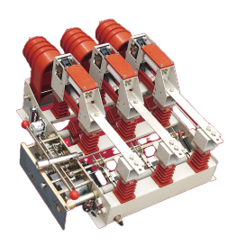
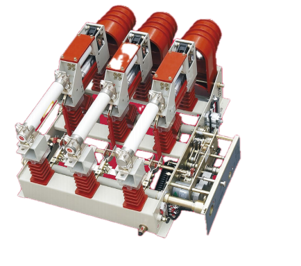
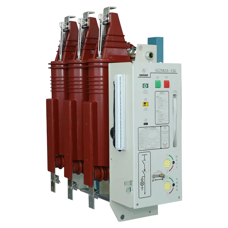
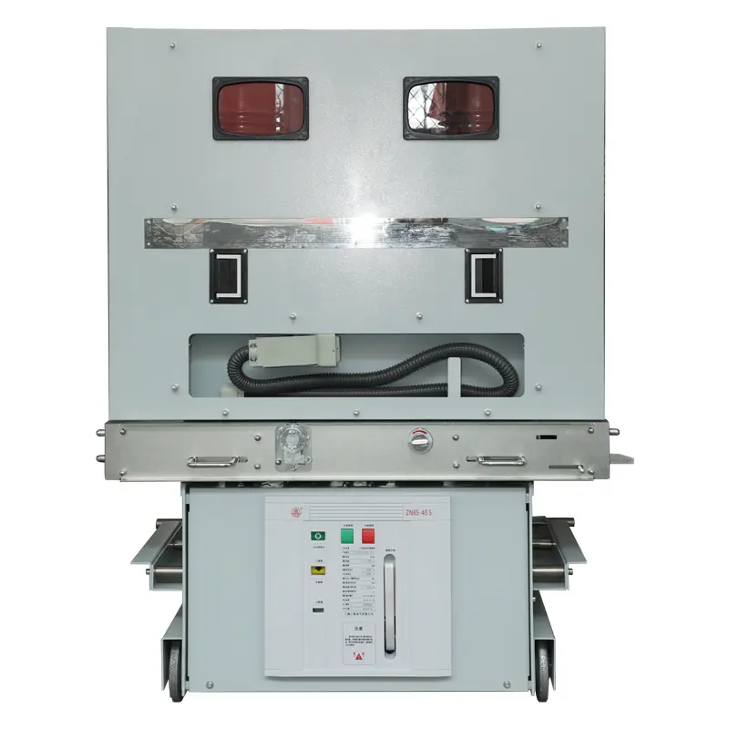
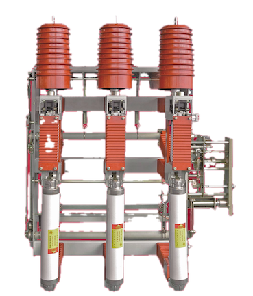
China manufacturer SanGao specializes in the R&D and Sales of the Indoor Type 24V Vacuum Load Break Switch-Fuse Combination Apparatus for over a decade. This is a high-voltage switching device that integrates a vacuum load break switch in series with current‑limiting fuses into a single assembly. The combination has the load switching capability of the load break switch and relies on the fuses for fault current interruption.This Apparatus are broadly used as a high‑value solution for protecting distribution transformers in medium‑voltage networks.
Send Inquiry
Product Description
As a control and protection device for three‑phase AC 50Hz 24kV distribution systems, the Indoor Type 24V Vacuum Load Break Switch-Fuse Combination Apparatus supplied by SanGao has been widely adopted in substations of industrial and mining enterprises, commercial buildings, and particularly in looped network distribution systems. The apparatus ingeniously combines the strengths of the vacuum load break switch and the limiting fuse. When compared with a vacuum circuit breaker, the combination offers a more compact, cost‑effective solution for distribution‑level applications, with simpler construction, easier maintenance, lower cost, and reliable operation.
Main Purpose
The Indoor Type 24V Vacuum Load Break Switch-Fuse Combination Apparatus is an indoor switching device for three‑phase AC 50Hz 24kV power distribution systems. It is composed of a vacuum load break switch connected in series with current‑limiting fuses. The load break switch section makes and breaks load currents, closed‑loop currents, and no‑load transformer currents. The fuse section handles overload and short‑circuit current interruption. The apparatus has been widely used in substations of industrial and mining enterprises, buildings, and especially in looped network distribution systems.
What's its superiority?
The combination of vacuum load break switch and fuse delivers a cost‑performance balance that neither device can achieve alone. By combining the load switching capability of the switch with the fault clearing capability of the fuse, the apparatus provides protection approaching that of a circuit breaker at a cost significantly lower. This makes it the preferred solution for distribution transformer protection in 10‑24kV systems.Transformer Capacity Selection Guide
Selecting the correct protection configuration depends on transformer capacity. The following guidance applies to 10‑24kV distribution transformers:
800 kVA and below: Standard type load break switch‑fuse combination (air‑insulated type) is adequate. The fault current level at this capacity is within the interrupting capability of standard fuses.
800 kVA to 1250 kVA: Vacuum or SF₆ insulated load break switch‑fuse combination recommended. These types support more frequent operation and provide higher fault withstand capability.
Above 1250 kVA: A full vacuum circuit breaker with relay protection is generally required due to the higher fault current levels and the need for more sophisticated protection coordination.
Routine Maintenance and Operation
Proper maintenance extends apparatus service life and ensures reliable protection. The following practices are recommended.
1. Regular operation test
Perform a switching operation cycle (open and close) at least once per month to maintain mechanism flexibility and verify correct interlock function.
2. Electrical testing
Conduct circuit resistance and insulation resistance measurements annually. Record data to establish trends – a gradual increase in contact resistance or decrease in insulation resistance indicates deterioration requiring attention.
3. Visual inspection and cleaning
Regularly clean insulating surfaces to remove dust accumulation. Check for condensation, particularly in high‑humidity environments. For units installed in outdoor enclosures, inspect seals for aging and replacement.
4. Fault records
Maintain a fault log documenting each fuse operation and the conditions under which it occurred. Analysing fault patterns helps identify recurring issues, allowing targeted maintenance planning and reducing unplanned downtime.
Normal Working Environment
The Indoor Type 24V Vacuum Load Break Switch-Fuse Combination Apparatus is designed for the following installation conditions.
Ambient temperature: Upper limit +40°C; lower limit -25°C (storage permitted at -30°C).
Altitude: ≤ 1000 m above sea level.
Relative humidity: Daily average ≤ 95% at +20°C; monthly average ≤ 90% at +20°C.
Earthquake intensity: ≤ 8 degrees.
Environmental conditions: Free from corrosive and flammable gases or vapours; free from intense vibration. Pollution grade: Class II.
Installation outside these specified conditions requires derating or additional protective measures.
Product Features
Significant cost advantage
Equipment cost and associated investment are lower than circuit breakers. This is a highly cost‑effective distribution protection solution, offering near‑breaker protection at switch cost.
High short‑circuit breaking capacity
The current‑limiting fuses can interrupt short‑circuit currents up to 50‑63 kA – far exceeding the switch's own capability. This provides robust fault protection for distribution networks.
Fast protection speed
The fuse melts before the short‑circuit current reaches its peak. Total clearing time is less than 20 ms, protecting device operation safety.
Simple, reliable operation
The Indoor Type 24V Vacuum Load Break Switch-Fuse Combination Apparatus supports frequent operation. Fuse protection is purely mechanical – it does not rely on control power, auxiliary relays, or batteries, ensuring protection even during auxiliary power loss.
Low maintenance demand
Simple construction requires no regular calibration of protection relays. Routine attention focuses on fuse condition checks and visual inspection, reducing maintenance workload.
Application Scenarios
Ring main units (RMUs) and compact substations: The 24V Vacumn Load Break Switch and Fuse Combination Apparatus Unit is the primary switching and protection device in RMUs and box‑type substations, widely used in urban and industrial distribution networks.
Distribution transformer protection: As a switch‑fuse combination, it provides economic and effective protection for distribution transformers up to 1250 kVA, combining load switching with short‑circuit clearing.
Line sectioning and interconnection: Used as sectioning and tie switches for overhead lines and cable feeders.
Industrial and commercial installations: Suitable for substations in industrial plants, commercial buildings, and mining operations.
Rural distribution networks: In long rural feeders, voltage drop during peak periods can affect end‑user voltage quality. Installation at strategic sectioning points allows operators to isolate faults, reduce outage zones, and manage voltage profiles through capacitor bank switching. The low maintenance requirement is critical where service crews travel long distances.
FAQ
Q1: After fuse operation, does the switch mechanism require recalibration or special resetting before re-energizing?No recalibration is needed. After replacing the blown fuse, the switch can be reclosed via the normal manual or electrical spring-charging procedure. The striker‑pin trip mechanism is a one‑time mechanical actuator; it automatically resets when the switch is reclosed. However, always confirm that the fault condition has been cleared before restoring supply.
Q2: What is the recommended procedure if the 24V Vacuum Load Break Switch-Fuse Protection Device has been idle (not operated) for more than six months?
Perform at least three consecutive open‑close operations without load to exercise the mechanism and distribute lubricant. This helps prevent sticking due to prolonged static contact. After these dry runs, measure contact resistance and insulation resistance to verify that the vacuum interrupter and main circuit have not degraded. Record the values as a baseline for future comparison.
Q3: How can I verify the vacuum integrity of the interrupter without specialised vacuum test equipment?
While a dedicated vacuum gauge is the most accurate method, field verification can be performed by applying the rated AC withstand voltage across the open contacts for 1 minute at reduced voltage (80% of factory test level). A sustained internal glow or audible discharge indicates vacuum loss. Alternatively, a portable partial discharge detector can identify interrupter degradation during routine maintenance. SanGao provides a detailed vacuum‑check guide with each unit.
Q4: What is the typical service life of the vacuum interrupter, and when should it be replaced?
The interrupter is designed for 20,000 mechanical operations and 10,000 load current interruptions at rated current. Replacement is indicated when contact wear exceeds 3 mm (measured by stroke change), or if contact resistance increases by more than 30% above the initial factory value under identical test conditions. SanGao offers replacement interrupters with matching performance characteristics.
Q5: Does the apparatus support installation above 1000 m altitude, and what derating applies?
Yes, but derating is required. For each 100 m above 1000 m, the rated current must be reduced by 1.5%, and the rated insulation level decreases by approximately 6.5% per 1000 m. For installations at 2000 m, the current rating reduces to approximately 85% of nominal, and the withstand voltage test level should be adjusted accordingly. SanGao can supply altitude‑specific coordination data upon request.
Main Technical Parameters
| No. | Item | Unit | SG25-24D/T630-20 | SG25-24DR/125-315 |
|---|---|---|---|---|
| 1 | Rated voltage | kV | 24 | |
| 2 | Rated frequency | Hz | 50 | |
| 3 | Rated current | A | 630 | 125 |
| 4.1 | Rated insulation level – 1 min power frequency withstand voltage (phase-to-earth/phase-to-phase / isolating distance) | kV |
Arc-extinguishing chamber opening distance 65:phase-to-earth, phase-to-phase 65;isolating distance 79 |
|
| 4.2 | Rated insulation level – Lightning impulse withstand voltage (peak) (phase-to-earth/phase-to-phase / isolating distance) | kV |
Phase-to-phase, phase-to-phase 125;isolating distance 145
|
|
| 4.3 | Rated insulation level – Creepage distance of external insulation | mm/kV | ≥20 | |
| 4.4 | Rated insulation level – Air clear distance (phase-to-earth / phase-to-phase) | mm | Phase-to-earth > 200;phase-to-phase 200 | |
| 5 | Rated short-time withstand current (thermal stability current) | kA | 20 |
|
| 6 | Rated duration of short circuit (thermal stability time) | s | 4 |
|
| 7 | Rated peak withstand current (dynamic stability current) | kA | 50 |
|
| 8 | Rated active load breaking current | A | 630 |
|
| 9 | Rated closed-loop breaking current | A | 630 |
|
| 10 | Rated cable charging breaking current | A | 10 |
|
| 11 | No-load transformer breaking capacity | kVA | 1250 |
|
| 12 | Rated short circuit breaking current | kA | — | 31.5 |
| 13 | Rated transfer current | A | — | 2000 |
| 14 | Model of fuse | — | — | S □ M □ J-SY24/ □ |
| 15 | Output energy of striker | J | — | 2–5 (medium) |
| 16 | Rated short circuit making current | kA | 50 | |
| 17 | Rated short circuit closing current of earth switch (dynamic current) | kA | 50 | |
| 18 | Rated short-time withstand current (thermal stability current) of earth switch | kA | 20 | |
| 19 | Rated duration of short circuit of earth switch (thermal stability time) | s | 2 | |
| 20 | Rated voltage of auxiliary circuit | V | AC, DC / 220, 110 | |
| 21.1 | Mechanical life – Vacuum arc-extinguishing chamber / isolating distance | times | 10000 / 2000 | |
| 21.2 | Mechanical life – Earth switch | times | 2000 | |
Data of Energy Storage Motor
| Model | Rated Voltage (V) | Rated Current (A) | Rated Power (W) | Normal Operating Voltage Range |
|---|---|---|---|---|
| ZYJ-220-66-208 | DC220 | 0.7 | 70 | 85% – 110% of rated voltage |
| ZYJ-110-66-208 | DC110 | 1.5 |
Data of Opening Coil
| Item | Rated Voltage (V) | Coil Power (W) | Normal Operating Voltage Range |
|---|---|---|---|
| Opening coil | DC220、DC110 | 550 | 65% – 110% of rated voltage |
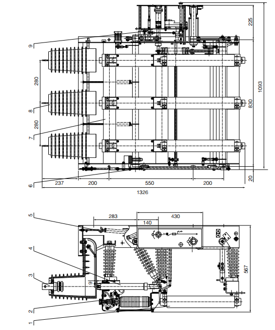
Outline and Installation Size
Related Category
Send Inquiry
Please Feel free to give your inquiry in the form below. We will reply you in 24 hours.