
- English
- Español
- Português
- русский
- Français
- 日本語
- Deutsch
- tiếng Việt
- Italiano
- Nederlands
- ภาษาไทย
- Polski
- 한국어
- Svenska
- magyar
- Malay
- বাংলা ভাষার
- Dansk
- Suomi
- हिन्दी
- Pilipino
- Türkçe
- Gaeilge
- العربية
- Indonesia
- Norsk
- تمل
- český
- ελληνικά
- український
- Javanese
- فارسی
- தமிழ்
- తెలుగు
- नेपाली
- Burmese
- български
- ລາວ
- Latine
- Қазақша
- Euskal
- Azərbaycan
- Slovenský jazyk
- Македонски
- Lietuvos
- Eesti Keel
- Română
- Slovenski
- मराठी
- Srpski језик

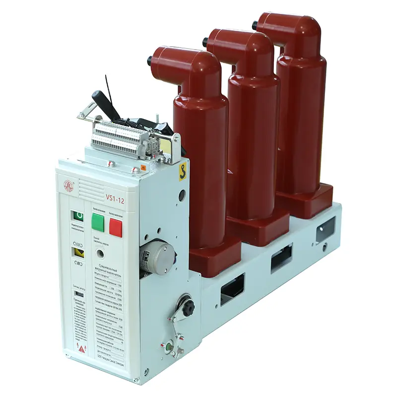
Do You Know the Key Considerations for Installing a Side-Mounted Indoor Vacuum Circuit Breaker?
As the core protection device of the power system, the installation quality of the Side Mounted Indoor Vacuum Circuit Breaker directly affects its operational safety and lifespan. During the construction phase, it is imperative to strictly follow the specifications and focus on the following aspects:
1. Environmental Assessment and Preparation
Environmental Requirements: The installation environment for a side-mounted indoor vacuum circuit breaker must be clean, dry (relative humidity ≤ 85%, no condensation), well-ventilated, and free of flammable, explosive, corrosive gases, and conductive dust. The ambient temperature must be strictly controlled within the permissible range of -5°C to +40°C. Space Reserve: Ensure sufficient space in the distribution cabinet to accommodate the circuit breaker dimensions, operating handle range (unimpeded closing/opening operations), and specified arcing safety distance requirements (refer to the product manual). The cabinet door must be fully openable for easy maintenance. Foundation Inspection: The mounting bracket must be secure, flat, and level, with sufficient rigidity and strength to withstand the impact of circuit breaker operation and short-circuit forces. The cabinet structure must be free of deformation, and the mounting holes must be precisely aligned.
2. Precise Installation and Secure Fixing
Lifting and Handling: Use appropriate lifting equipment and handle the circuit breaker gently, avoiding excessive vibration and impact. Do not lift or pull on the insulating rod or operating handle. Precise Positioning: Push the circuit breaker body accurately into the mounting rail or bracket, ensuring it is fully aligned with the fixing holes. Secure Fixing: Use bolts, washers, and locking elements (such as spring washers and locknuts) that meet the manufacturer's specifications and meet the specified tightening torque, tightening them evenly and diagonally in stages. Any looseness will increase operating vibration and endanger safety.
3. Reliable Electrical Connections
Busbar/Cable Compatibility: The connecting busbar or cable specifications must be designed to match the rated current and short-circuit withstand capability of the circuit breaker, and the connecting surfaces must be smooth and clean. Contact Surface Preparation: Thoroughly remove any oxide layer or dirt on the conductor connecting surfaces. Apply a generous amount of high-quality conductive grease (electrical compound grease) to significantly reduce contact resistance and prevent oxidation. Torque Control: This is crucial! Use a calibrated torque wrench to tighten all connecting bolts, including those at the input and output terminals, strictly to the torque value specified by the circuit breaker manufacturer. Over-tightening can cause poor contact and overheating, while over-tightening can damage the terminals or threads.
4. Operating Mechanism Inspection
Manual Operation Verification: With the Side Mounted Indoor Vacuum Circuit Breaker completely de-energized, repeatedly perform slow manual charging, closing, and opening operations to ensure smooth and flexible operation, no sticking or abnormal noise, and accurate and clear position indication (open/closed/charging). Auxiliary Switch Verification: Check that the auxiliary switch's on/off status (normally open/closed) accurately corresponds to the main switch position and that the wiring is correct and secure.
5. Post-Installation Functional Commissioning
Insulation Test: Use a megohmmeter appropriate for the voltage rating of the Side Mounted Indoor Vacuum Circuit Breaker to test the main circuit insulation resistance to ground and between phases as required by regulations (e.g., main circuit: 1000V range, ≥100MΩ). Mechanical property measurement (if conditions permit): It is recommended to use dedicated instruments to measure parameters such as opening/closing time, speed, contact opening distance, overtravel, bounce time, synchronicity, etc. (for example, contact opening distance should generally be within the range of 8±1mm). The data should be compared with the factory report and within the acceptable deviation. No-load operation test: Before the final power is applied, perform several electrical operations (closing and opening) to reconfirm the reliability of the operation and the correctness of the position indication. Protection and signal circuit verification: Simulate signals to test the linkage logic and signal transmission accuracy between the circuit breaker, relay protection device, and central signal system.